This procedure is intended to be readily calculated by. Requires a PVC liner to protect it from petroleum spills. abutment design example.
Abutment Design Example, Integral abutments are the preferred abutment type and the Department continues to strive to increase the number of structures eligible for integral design. This procedure is intended to be readily calculated by. No consideration is given to the effect of the.
 Bridge Abutment Design Types Examples Video Lesson Transcript Study Com From study.com
Abutments that do not meet the design guide criteria these figures may not accurately reflect the final abutment design. It is considered suitable for common residential situations with competent soils. Total horizontal load on each abutment 852 43kNm.
Design Step 7 Design of Substructure Prestressed Concrete Bridge Design Example Task Order DTFH61-02-T-63032 7-2 One group of states design the piles of an integral abutment to resist only gravity loads applied to the abutment.
If no fixed abutment is used then the movement will take place at both ends so. The abutments using a unit strip method. Unlike the bridge abutment the earth-retaining structures are mainly designed for sustaining lateral earth pressures. Abutment and substructure design. Requires a concrete cap slab to distribute traffic loads. For skewed bridges increase the abutment thickness to maintain a minimum of 5 inches between the beam end and the approach slab seat See Figure 11112.
Another Article :

Requires a concrete cap slab to distribute traffic loads. For skewed bridges increase the abutment thickness to maintain a minimum of 5 inches between the beam end and the approach slab seat See Figure 11112. This design example is basically the same as Track 1 Example 1 with additional construction control involving pile retaps or restrikes at 3 days after EOD. Integral abutments are the preferred abutment type and the Department continues to strive to increase the number of structures eligible for integral design. Abutment Design Example to BD 30. Fm 3 34 343 Chapter 7.

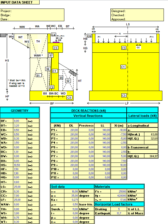
Select Preliminary Abutment Dimensions Design Step 73. The abutments using a unit strip method. Abutment Design Example to BD 30. Changed Bridge End Selection flow chart to match 2009 VTrans LRFD Structures Manual and changed all detail titles that read Type J to Type A to match the 2009. My Service 373 kft Mx Service 188 kft Tz Service 352 kft Figure 6 - Abutment Eccentricities. Bridge Abutment Calculations Spreadsheet.

Tension Ps 415 kip Shear Vs 300 kip 899 ft. Addi-tional guidelines related to scour protection and layout are also included. Abutment Design Example to BD 30. My Service 373 kft Mx Service 188 kft Tz Service 352 kft Figure 6 - Abutment Eccentricities. The bridge site is located south east of Oxford. Bridge Design Bridge Abutment Design Example To Eurocodes.

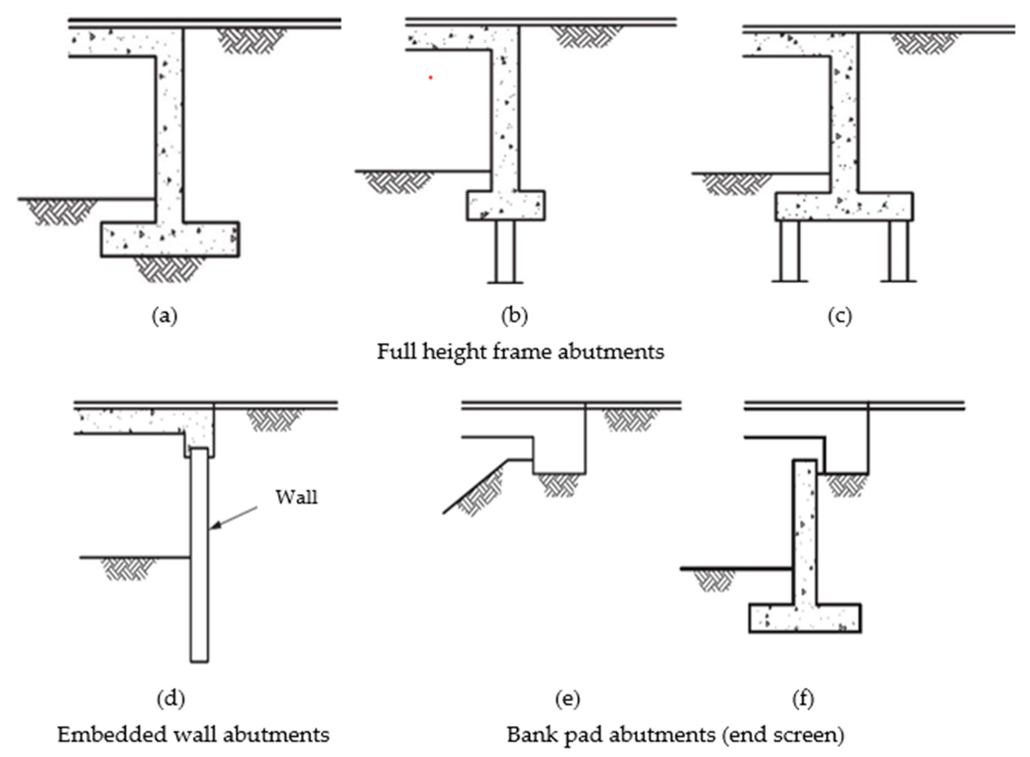
The following worked example uses a simplified LRFD design procedure with load and resistance factors taken from B1VM4. Abutment and substructure design. Cantilever Gravity Counterfort Mechanically-stabilized earth Stub semi-stub or shelf Open or spill-through Integral or semi-integral. It should be noted that the resistance factors with special consideration of pile setup are for 7-day retap. Geometry Use a minimum thickness of 3 feet for the abutment stem. Model Dimensions Of A 45 Wing Wall Abutment Of The Pile Supported Form Download Scientific Diagram.

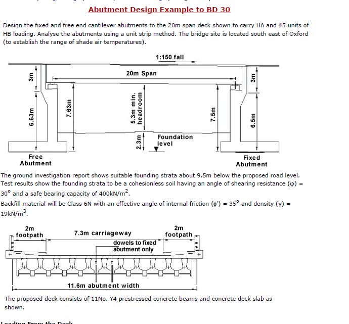
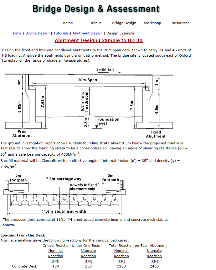
Where Cu Undrained shear strength of soft layer psf. My Service 373 kft Mx Service 188 kft Tz Service 352 kft Figure 6 - Abutment Eccentricities. Design the fixed and free end cantilever abutments to the 20m span deck shown to carry HA and 45 units of HB loading. Option 2 - Sliding Bearing. Select Preliminary Abutment Dimensions Design Step 73. Bridge Abutment Design Types Examples Video Lesson Transcript Study Com.

Addi-tional guidelines related to scour protection and layout are also included. This procedure is intended to be readily calculated by. Requires a concrete cap slab to distribute traffic loads. FS 2Cu 414Cu gamaDstantheta Hgama. Abutment Design for Small Bridges Purpose This technical supplement presents a procedure for determining the ultimate and allowable bearing capac-ity for shallow strip footings adjacent to slopes. Applied Sciences Free Full Text Geotechnical Design Practices And Soil Structure Interaction Effects Of An Integral Bridge System A Review Html.

Total horizontal load on each abutment 852 43kNm. Select Optimum Abutment Type Design Step 72. Addi-tional guidelines related to scour protection and layout are also included. Spread footings usually have a design orientation normal to the footing. Those structures have been widely used in highway construction. Bridge Abutment Design Example.

Total horizontal load on each abutment 852 43kNm. The abutments using a unit strip method. Unlike the bridge abutment the earth-retaining structures are mainly designed for sustaining lateral earth pressures. Note that for shaft and some pile foundation designs the shaft or pile may form the column as well as the foundation element. Analyse the abutments using a unit strip method. Bridge Abutment Design Solved Example Engineering Books.
Settlement Analyses Task 4Bearing Capacity. In this chapter several types of retaining structures are presented and a design example is also given. Since bridge loads are longitudinal and transverse skewed superstructure loads are converted using. Addi-tional guidelines related to scour protection and layout are also included. Abutment design spreadsheet can be used to obtain design forces for abutment or retaining wall. Nzta Govt Nz.

More expensive than sand backfill but could cause other cost savings. The bridge site is located south east of Oxford to establish the range of shade air. Integral abutments are the preferred abutment type and the Department continues to strive to increase the number of structures eligible for integral design. Design Step 7 Design of Substructure Prestressed Concrete Bridge Design Example Task Order DTFH61-02-T-63032 7-2 One group of states design the piles of an integral abutment to resist only gravity loads applied to the abutment. Where Cu Undrained shear strength of soft layer psf. Bridge Design Bridge Abutment Design Example To British Standards.

The bridge has a 160 feet span with a 15 degree skew. Requires a concrete cap slab to distribute traffic loads. The bridge has a 160 feet span with a 15 degree skew. Corrected an error in the design example. Those structures have been widely used in highway construction. Pdf Article 5 Detail Design Of Bridge Abutment In Aashto Lrfd.

Select Preliminary Abutment Dimensions Design Step 73. Abutment Design Example to BD 30. Analyse the abutments using a unit strip method. Induces virtually no horizontal pressures on abutment Prudent to design for some amount of horizontal pressure. Full Height Abutment on Spread Footing. Bridge Abutment Design Example.

This design example demonstrates how to estimate the nominal driving resistance. Abutment Design Example in details. Global Stability Task 3. Design the fixed and free end cantilever abutments to the 20m span deck shown to carry HA and 45 units of HB loading. No consideration is given to the effect of the. 3 Example Of A Stub Abutment System Commonly Used By Many State Dot S Download Scientific Diagram.

If no fixed abutment is used then the movement will take place at both ends so. Since bridge loads are longitudinal and transverse skewed superstructure loads are converted using. The bridge has a 160 feet span with a 15 degree skew. This design example is basically the same as Track 1 Example 1 with additional construction control involving pile retaps or restrikes at 3 days after EOD. Where Cu Undrained shear strength of soft layer psf. How To Evaluate Bridge Abutments Fprimec Solutions Inc.

Where Cu Undrained shear strength of soft layer psf. It is considered suitable for common residential situations with competent soils. Abutment foundations must also be. Integral abutment bridges eliminate the need for joints in bridge decks and thereby provide better protection for the superstructure and substructure from water and salt damage. Tension Ps 415 kip Shear Vs 300 kip 899 ft. Bridge Design Bridge Abutment Design Example To British Standards.


